I’m Chris Moulding (amateur radio callsign G4HYG) and I’m working on a few odd radio projects at Cross Country Wireless. I’ll use this blog to show the world what I’m up to. Some of the best ones are the ones that don’t make it out of the workshop…
Heathkit HW-7 part 5 – output filter
Looking at the original 1972 manual for the Heathkit HW-7 the specification for spurious and harmonics is only 25 dB down on the transmit carrier. Modern commercially made amateur radio equipment is designed to meet the ITU specification for HF amateur radio equipment which is 43 + 10 log (PEP), or 50 dB, whichever is less stringent.
Testing the transmit output on a spectrum analyzer showed that they were not generous with the specifications the second and third harmonics were only just 25 dB down.
At Cross Country Wireless one of our filter products for the professional market is a bandpass filter that uses a combination of cascaded high pass and low pass filters. In the filter textbooks this is the filter that’s mentioned in the first few paragraphs on bandpass filters but is then rejected as being far too difficult to model mathematically. As long as the high and low pass filters are well spaced in cutoff frequency we can design and manufacture some very effective filters.

The photograph shows a bandpass filter designed for the HW-7 using this technique. The high pass filter cuts off at 6.5 MHz and the high pass filter cuts off at 25 MHz. The PCB board is the one we use in the filters. What is not obvious is that there is a plated through hole at each of the crossing points on the board connected to an identical grid on the other side. When the board is bolted into an enclosure the grid is very effectively RF grounded to the enclosure. BNC connectors were fitted for testing on the network analyzer.
Obviously as it’s not being built for a paying customer I’m using a board that’s been previously used to build a prototype hence all the excess solder on the board. What’s the old saying…a cobbler’s son is always the worst shod!

The bandpass filter does work well. The network analyzer display is covering from 3 to 53 MHz (you can see the 50 MHz marker on the right of the display). The vertical scale is 10 dB per box so at 3.5 MHz the filter is 68 dB down. In the medium wave band the attenuation is even higher. On another transceiver the strongest local AM broadcast station on 1458 kHz cannot even be detected in SSB mode with the filter in.
For the transmit harmonics the bandpass filter cuts off well and it will certainly help the HW-7 meet the modern spurious and harmonic specification. The return loss (VSWR) curve could be better but it would need more time to align it (what did I say earlier about the cobbler’s son?).
It’s all very well quoting specifications and dB levels etc, etc but let’s see if I can give a visual aid to what the filter can do on receive.

Just behind the workshop we have a 15m vertical wire antenna suspended by a tree. This uses a 9:1 current balun to give a rough match to 50 ohms. Here is the antenna fed into a 50 MHz oscilloscope just as the front end preselector circuit in the HW-7 would see it. The oscilloscope is set to 20 mV per box on the vertical scale so the peaks are filling the screen giving 200 mV peak to peak. Yes, that’s 0.2 VOLTS peak to peak!

Putting the bandpass filter in circuit the signal level drops to 10 mV peak to peak. It’s still a high level but any receiver never mind the HW-7 only stands a chance of working once most of the unwanted RF energy from the antenna is filtered out.
One of the reasons I’ve added this filter is that eventually when it’s completed I’d like to take the HW-7 on a SOTA Summits on the Air activation up Winter Hill. Winter Hill has several transmitter masts including the main TV, FM and DAB transmitter mast with megawatts of effective radiated power coming from it.
I often take prototype products up there for testing on the basis that it they work up there they should work anywhere.
Heathkit HW-7 part 4 – receiver filter
Now that the Heathkit HW-7 is working close to the original specification with all the 45 year old carbon resistors changed for 2019 metal film resistors I can now look at some modifications to bring it up to modern standards.
The first thing I want to look at is the receiver filter. The HW-7 has a simple LC low pass filter immediately after the 40673 mixer so lets see how it performs.
To do this I fed a wideband noise source into the antenna input suitably attenuated so that it didn’t overload the receiver. I then fed the audio from the headphone socket into an external sound card connected to my Windows laptop. I then opened the Spectrum Lab audio analysis program to look at the filter bandwidth and response.

The existing filter is fairly flat from 200 to 1200 Hz at the -6 dB points with the peak at 1000 Hz. It’s not a bad filter for such a simple design as the stopband from 3500 Hz is 50 dB down.
It’s probably a bit wide by modern standards and later I want to modify the transceiver so that it has a correct 750 Hz offset between transmit and receive so can the filter be modified to sharpen it up?

I modeled the existing filter in the Elsie filter program and came up with some capacitor value changes that reduced the loss between the mixer and audio amplifier by 5 dB and sharpened the filter. The peak of the filter is now at 750 Hz and the -6 dB points are at 400 and 1000 Hz. The stopband figure remains the same at 50 dB down.
The changes look very subtle on the display as the 5 dB reduction in loss tends to hide the changes but it does sound a lot better listening to CW on air.

Only three capacitors were changed, C5 is now 0.47 uF from 0.22 uF, C9 is now 0.47 uF from 0.1 uF and the coupling capacitor C52 is now 0.22 uF from 0.05 uF.
I did try experimenting by changing the inductor bypass capacitor C7 from 0.01 uF to 0.1 uF. This gave a really sharp cutoff above 1000 Hz but the stopband figure reduced from 50 dB to only 30 dB so while it would sound great working weak signals at sunspot minimum it would fail listening to a band full of strong contest signals.
With simple filters like this it’s tricky to get the right balance but you can get close with modern computer modeling and measurement tools.
Heathkit HW-7 part 3 – resistors
Before I start doing the fun stuff like adding a new mixer or tuning the audio filter I thought that I had better get down to basics.
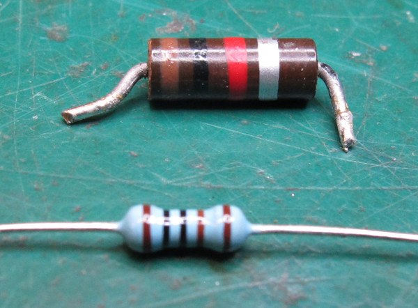
Earlier I mentioned that vintage carbon resistors tend to fail by slowly increasing their resistance value and the only resistor I had removed so far showed signs of that. It also had an intermittent fault on the receiver where the mixer appeared to cut off when the PCB was pressed.
Today I removed all the old carbon 10% tolerance resistors and replaced them with modern metal oxide 1% resistors. I measured the value of each old resistor to compare it to it’s nominal value.
It took a bit longer than my lunch time to do it, it felt like I was building the kit from new!
Only two low value resistors remained within the 10% tolerance rating. All the others were 20 to 30% higher in value than what they should have been.
It was worth doing as testing after the work revealed that the receiver sensitivity had increased considerably and the VFO stability was improved especially immediately from switch on. The intermittent fault had gone so it was probably a dry joint on one of the old resistors.
With the correct resistor values in circuit it’s probably now working as the Heathkit design engineers intended back in 1972.
Heathkit HW-7 project part 2
The Heathkit HW-7 CW transceiver I had recently acquired had a problem with the VFO, it wasn’t oscillating. I’m going to use these blog posts to record what I find so that it might help others trying to renovate or restore these transceivers.
I found two faults with the VFO. The 350 uH choke has a high resistance of 12 ohms so I replaced it with a modern 470 uH choke.
The 47k ohm 10% tolerance resistor between the VFO FET gate and ground measured high at 58 k ohm. I remember back to valve or tube equipment of this era that also used carbon resistors like these. The resistors usually failed with the resistance value drifting high and I always though it was due to the heat and high voltage in that equipment. It looks that carbon resistors aged around 45 years also start to fail that way.
I replaced it with another 47 k ohm resistor. In the equipment we manufacture we use 1% metal oxide resistors and as far as I know we have never had one fail in the many thousand resistors we have used. It’s one area which has really developed over the years. I might look at “blueprinting” the HW-7 by replacing all the carbon resistors with 1% metal oxide resistors.
Now the VFO was working I ran through the alignment of the set. I found three dry solder joints around the multiplier coils. I also found dry solder joints on the coils themselves where the coil wires were soldered to the mounting pins. Using a solder sucker to remove the old solder and flux and replacing it with new after checking the wires were tinned correctly fixed the problems.
Now it was working I started to go through the list of Heathkit service modifications. The first modification was to remove R1 100 k ohm and short C6 100 pF with a short piece of wire. This really reduced the noise produced by the 40673 mixer and I could hear a 0.5 uV signal from the signal generator clearly on all three bands.
I found that the alignment was quite critical to get the best performance on receive, maybe some more resistors have gone high.

The next service modification was to fit a 220 k ohm resistor and 100 nF capacitor in series between pin 4 and pin 5 of the CA3035 IC. A 1 uF capacitor was also fitted between pin 6 of the CA3035 IC and ground. I’ve shown this in the photo above as it’s quite difficult to work out which pin is which from underneath the PCB with an early round IC. This modification reduces the gain slightly but the background noise from the IC almost disappears. It is well worth doing this mod.
I decided to do my first modification. The sidetone level was too high and most other mods to the HW-7 just hack the board to add a 10 k ohm pot or similar to turn it down. In my mod I replaced C46 0.05 uF with a 10 k ohm resistor and R34 33 ohm with a 100nF capacitor. This now acts as an RC filter that filters the tone but also attenuates the sidetone level. This gives a comfortable level that also sounds a bit cleaner too.
It may be a lunchtime project but I spent most of the afternoon and evening listening on headphones to it. Now that it’s working it’s surprisingly good for such a simple direct conversion receiver. The audio filtering is more suited to SSB than CW so I’ll probably look at that next while I’m waiting for some replacement PA transistors to arrive. The 40673 mixer does suffer from intermods and you have to be careful with the preselector to peak the amateur band rather than the adjacent broadcast band. I’ll look at replacing the mixer with a modern balanced switching mixer. I’ve got some ideas for that that won’t take too many milliamps of current.
An interesting point is that a resonant antenna like a dipole acts as a reasonably sharp preselector so the 40673 mixer intermod tuning problem seems acceptable for casual use with one. When I took it home and used it on the wideband Terminated Inverted U there was no selectivity in the antenna and you can tune the preselector and easily note all the HF broadcast bands. It really does need a better mixer!
The VFO is very stable and is fine for CW and SSB reception. Heathkit did a good job with that.
So far so good, it’s a fun receiver to use…
Heathkit HW-7… lunchtime project
Recently I’ve just bought a Heathkit HW-7 QRP CW transceiver off eBay.

Why you may ask when you have access to advanced SDR transceiver prototypes and other high end radio equipment?
Well sometimes it’s good to go back to basics and remember what radio was about when I started working in it.
The HW-7 was produced as a kit from 1972 to 1975. It was VFO controlled with a crystal transmit option CW transceiver covering the 40, 20 and 15m amateur bands. The RF output was around 1.5W but it’s main feature was the current consumption on receive at only 35 mA. Modern transceivers with synthesized frequency control, displays, DSP all eat power. The Yaesu FT-817 and FT-818 replacement take 400 mA on receive which is about the same as the this ancient HW-7 takes on transmit. Back in 1972 you could power a HW-7 with a pair of 6V lantern batteries for a week.

The listing on eBay stated that the seller had bought it as a project and never got around to looking at it. I’m sure that won’t happen here! It would be a nice project to bring it up to 21st century standards while still keeping the same low power consumption.

It looks in very clean unmodified condition but the rear phono plug and jack sockets show signs of rust so at some point in it’s long history it’s been stored somewhere damp. The only problem I can see is that the leads on one of the PA transistors have broken off, probably caused by a rough trip through the postal system shaking the large heatsink plate bolted to the transistor.
So for the first test with a temporary 12V cable soldered onto the back of the white Molex connector, an antenna connected via an adaptor and a Plantronics medium impedance headset plugged in the headphone jack.
Switch on and good, there is noise from the head phones, I can tune the preselector and get some broadcast stations breaking through (the HW-7 was legendary for that!) but I can’t tune any stations in with the VFO. There is no output on transmit but the sidetone is deafening (and I’m already deaf so it must be loud!).
With a suitable crystal in the crystal socket I can get 0.1W on 40m and 0.5W on 20m so it looks like the VFO is faulty.
What’s the old saying… amplifiers oscillate and oscillators don’t. This is going to be fun…
Project cancelled…
Sometimes development projects get cancelled for moral reasons rather than technical ones…
The contents of this unassuming box kicked off all sorts of problems at Cross Country Wireless back in 2014.
It’s the prototype of what was then the proposed Sentry SDR transceiver. This would have had a very wide frequency range from 1.8 to 1400 MHz with a power output of 5 to 10 Watts.
I had placed a few posts about it’s development on the Cross Country Wireless forum and had some interesting technical discussions about it.
The problems started when it was picked up by the Southgate Amateur Radio News as a news story. Nothing wrong with that they were just being good journalists and found a good news story.
The response from the amateur radio community was immediate and very positive. We were still some months away from production but most of the problems had been ironed out.
When we started getting a lot of interest from countries that didn’t issue amateur radio licenses we started to wonder what was going on. Especially when we received emails from countries that were under United Nations sanctions!
It would have been very easy for us to continue development of this transceiver and launch it as an amateur radio product. Even with the transmitter limited to amateur frequencies it would be naive to think that no one would hack into the hardware to give it full transmit coverage.
Unlike existing ham radio transceivers using superhet or DSP technology this was a software defined radio. It could become the perfect tool for electronic warfare. A user could receive and record the most heavily encrypted message and transmit it back 1000 times. Even the most sophisticated communication system would struggle to cope with that level of jamming. And we were about to put it on the market!
I took the decision to cancel the project. It was a hard one to make as I had spent a lot of time and money getting so far with the development. After announcing the cancellation I got a lot of complaints about it and suggestions that I should just carry on and build it anyway as others would do it. Many thought I could make a lot of money from it. Maybe so but I still think I did the right thing and I can sleep at nights!
Today (five years later) I opened up the prototype to take some photos for this blog.
It’s still in a working condition but it’s obviously a prototype cobbled together from several boards. The input and output filtering is a very simplified version of the proposed production version and just used soldered links to swap between three bandpass filters. As it stands it’s got filters for 20m, 6m and 2m. I did enter a 432 MHz contest with the 100 mW output from the driver amp with a separate filter and did surprisingly well.
Other than that I’m not going to go into any more detail about what’s inside it. I might just get it running on 6m again and keep it in the workshop for monitoring summertime Sporadic E propagation.
Old radio ideas revisited
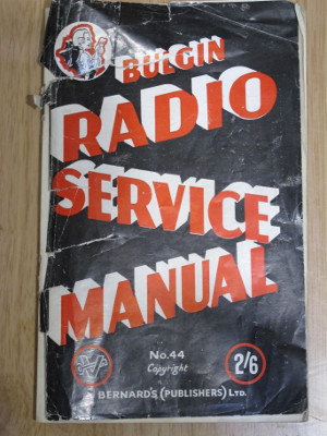
One of our local radio clubs (South Manchester Radio and Computing Club) has a very extensive library of old technical books donated by the members. Looking through it one evening I came across the Bulgin Radio Service Manual 1944-45 edition.
A few pages in I found an interesting article called “Aerial Efficiency” This described how to make a Doublet antenna for short wave listening using a selection of Bulgin radio components.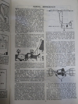
One line in the article stood out…”Varying forms of lead-in are employed, one of the simplest is twin-twisted rubber-covered wire, and very satisfactory indeed this is for experimental purposes.” It suggested that the rubber covered wire wasn’t good for outdoor use so ladder line was used for permanent installations.
Many years ago back in the 1970s I started my working life as an apprentice engineer for the local Electricity Board and I spend a few weeks with the house rewiring electricians removing the “twin-twisted rubber-covered wire” from a few houses. It didn’t last very long indoors and was fairly lethal with 240V AC applied to it as over time the rubber perished and started to crack up.
However the article got me thinking… What if I tried using modern materials for the “twin-twisted wire”. In the workshop I keep a few drums of 0.5mm and 0.8mm tri-rated cable from RS Components. This is a flexible copper wire of typically 16 or 32 strands but covered in a thick PVC insulation. It’s designed for use in industrial machinery and can withstand oil and other chemicals and a fair amount of heat. It’s called tri-rated as it’s meets the wiring regulations in Europe, USA and Canada and as it’s made in vast quantity it’s relatively cheap.
Twisting two wires together with a battery drill was a very easy and quick way of making a twin feeder. Entering the wire dimensions in an online calculator gave a characteristic impedance of 108 ohms for the 0.5mm wire so it should be possible to use it with a doublet antenna as the book suggested.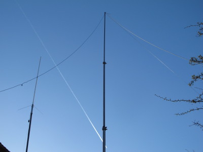
I soon whipped up a temporary doublet antenna to fit on the 9m Hilomast I use for antenna testing. The doublet elements are 8m long and the twisted pair feeder is 12m long to run down to the workshop. Two 20m long lengths of wire were used to make the feeder and the wire elements. The photo shows it on the mast just ty-wrapped on for testing. It certainly looks a lot better than ladder line and a lot cheaper too!
Using a Z Match tuning unit it could be tuned for an efficient match on all bands from 60m to 10m and would tune and match on 80m but it’s very short in terms of wavelength.
The most interesting observation is that because the majority of the electric field between the two wires in the feeder is within the PVC insulation the feeder can be run through a metal framed window closed onto the wire with no noticeable effect. I also tried running it on top of a metal cabinet again with no noticeable change to the tuner match or signal level. Try that with ladder line and it’s badly affected.
Testing with 150W on all bands through the tuner showed no adverse effects even when the metal window is closed on the feeder.
Of course any temporary antenna that works well becomes semi-permanent so it’s still up on the mast several weeks after the first test!
